Hierarchy
|
Master
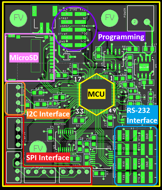
MicroSD Card InterfaceThe SD card is an SPI device that has 3.3V logic. Since the Xmega256A3 microcontroller runs on 3.3V logic, no level converters are needed, only four pins to interface with the card: Slave Select, Master-In-Slave-Out, Master-Out-Slave-IN, and Slave Clock. The connector we use also has a Card Detect pin. We use this to switch between storing data on the card, if it is there, or sending it to the Glider computers.Glider Computer InterfaceThere are two Computers on the Glider that we can interface with, the Linux board and the Science computer. We can pull the real time down to the master and transfer data that cannot be logged on the SD card using this interface. They only have RS232 serial interfaces, which do not run with 3.3V logic levels. RS232 logic uses Voltages of -3V to -12V as logic "1s" and 3V to 12V as logic "0s". This logic conversion is easily done with a pair of Maxim chips that we have included on the board.Slave InterfaceFor the Slaves we have two interfaces ready for use. There are the four SPI lines: SS, MISO, MOSI, SCK, similar to the MicroSD card. There is also a two wire I2C interface: Data, and Clock. The two interfaces are so Data and commands between the Slaves and the Master can be separated. I2C would be used for commands to the slaves and SPI to transfer Data between Master and Slaves. |
Slave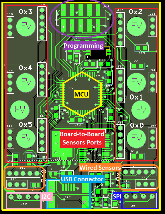
The slave is capable of connecting up to eight different sensors. It has six board-to-board ports and two auxiliary ports which can be used for sensors that can potentially be mounted elsewhere. Each sensor can be plugged into any port without the risk of being plugged in backwards due to the design of the board. The ports each have a specific address which is written on the top silk screen layer simplifying software management. There is a MicroUSB connection for benchtop sensing and live plotting of recorded data. This removes the need for a masterboard on sensing projects where a computer is at hand. |
SensorsThere are a total of ten different sensors that have been engineered for the sensing platform. Each sensor has either an I2C or Analog output. Since the glider consists of many other systems besides this sensing platform, recording current consumption was top priority. Most of the other sensors were developed for use in other applications but still may used in the Glider to acquire some unique readings.
List of Developed Sensors |